I have young children at home, who are now at the age where they get their own glass of water from the kitchen. They can walk to the cabinet that the glass is in. But they need to use a ladder to access the cabinet. For all of our three dimension-ness, most of our day to day navigation as people is in two dimensions. While there are oddballs and exceptions, for all sakes and purposes, the floors of a building can be considered each their own plane segment. There is a definite inside of that plane segment, and outside. And it doesn't matter if those definitions come from walls, railings, or a desire for a character to not plunge to their doom off of a precarious edge.
To change plane segments requires some sort of device. To give someone directions to travel from one room on the same floor to another room on the same plane, I don't need to factor in elevation or even consider any other planes. Oddball buildings where, say floor 10 is split in the middle, we model those as two floor 10's as different plane segments.
Plane segments are connected by staircases, elevators, tunnels, bridges, etc. And those devices have to factor in the third dimension. (Or for wormholes, possibly more dimensions.) But the fun part is that I can model those mathematically however I need, apart from the mathematical model of the plane segments themselves.
Having the layout for a section of a ship be a series of plane segments means I can record a map on two dimensions. I can also neglect the third dimension when routing NPCs around the ship and figuring out which spaces connect to which spaces.
As simplistic as this sounds, you will find that most 3d game engines that do route planning do essentially the same trick. (Thus game levels. Just saying.) But on a total-3d system, they still perform a slightly more enlightened simplification. 3d engines have a test for which polygons on the set are "routable." Routable polygons are connected together into networks. And sometimes those networks come together in comical ways. (Thus the MOB that walks halfway around the map to confront the player because there is a 6 inch gap in the floor between the player and MOB at the start of the fight.)
Deep, deep, deep in the logic of Fallout or Gears of War, is a dimensionless dot working out a solution across a network of 2 dimensional polygons to get within an action radius of another dimensionless dot.
The process of building this set varies with game engines. Some just import shapes from an external CAD model, apply a first order set of rules that take simple slope into account, and have the level designer "paint" on where the level needs to vary from from the ground rules.
For the Iliad, I am using a process developed for converting general arrangements drawings into a model into a digital map. My daytime gig collects oodles of data about a ship, and combines that information into an interactive map. That map, in turn, can go out to other people's software to give us data about how fire would spread, or flooding would tip things over. But the problem, as always, is getting data into the model in the first place.
The only consistent format that all Naval Architects, Ship Yards, and Subject Mater Experts seem to agree on is the 2d-general arrangements drawing. Yes, 3d CAD models exist. But the Naval Architects have something that makes sense for their analysis. Yards have something that makes sense for their planning software. And SMEs tend to have several formats at once that are mutually unsuitable for any other purpose. Heck, even the marketing people have a 3d format that only really makes sense for generating publicity photos.
Each expression in 3d has to throw out data to conform to the math model of whatever analysis is being performed. A math model describing the shrapnel path of a cruise missile exploding needs information about the material properties of a wall. A photo rendering engine only cares about the surface (and adding a pile of extra detail will slow it down horribly.) And some models need information above and beyond the physical material. Yes, two brackets may look visually the same, but if they are joined to the plates via rivets, bolts, or welds makes a HUGE difference to a structural model.
I am getting a little side tracked, so let us bring ourselves back to a world of plane segments, and tracing drawings.
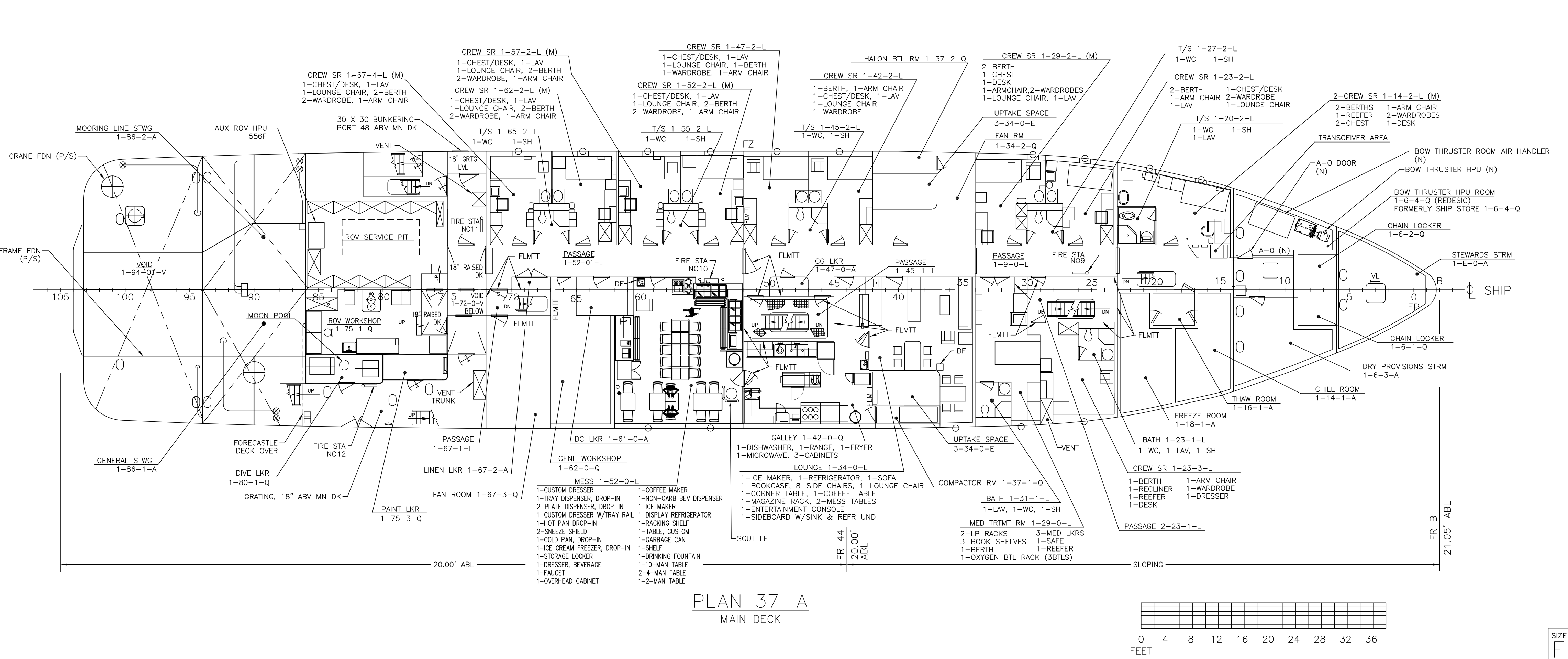
When I start to take a ship apart, I usually have to begin with a drawing like this:
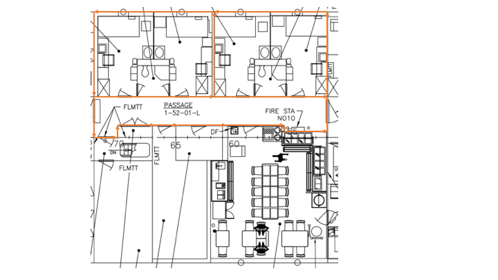
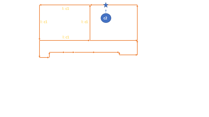
The next step is to start tracing the walls to capture what the model cares about as far as structural details. In this case, while the drawings show two cabins and a bathroom, for virtually every other aspect, these three spaces are one space for fire, flood, and damage control purposes:
With the walls traced, I then click on my mouse inside one of the regions carved up by the vectors. I have math tools that will find the closest wall to where I clicked, and then trace all of the vectors for walls around until I make a closed shape:
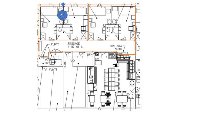
That shape will also mark the side of the walls so traced that face the compartment with the compartment's identifier. This allows other tools to play back the shape later.
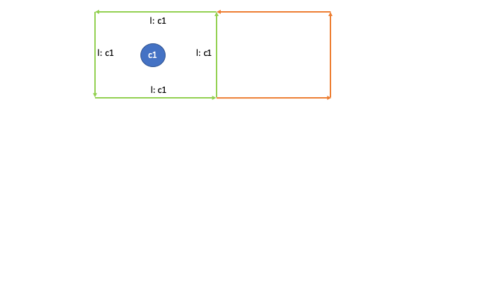
I then repeat the process with the next compartment:
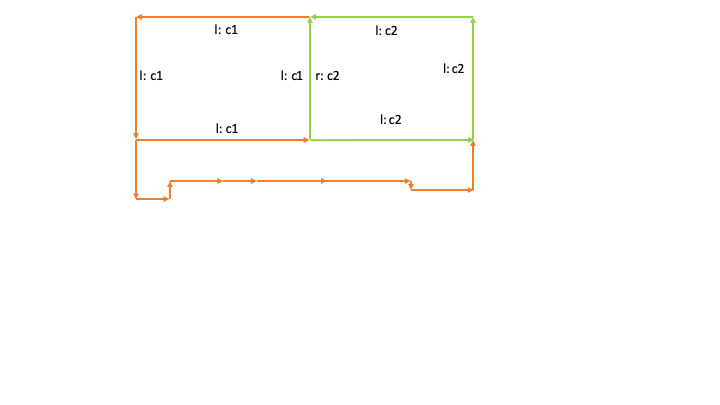
And in the end we can see that each of the walls has two sides, and each side side can be in a different compartment. We use the convention of "left" and "right" side because we have the luxury of knowing these are two dimensional vectors. (3d vectors and telling which side is which is impossible without a reference point.)
Fortunately for you and me, all of those math tools have been open sourced, and a few years ago I collected them together into a package called Odielib. If you are curious, most of the groundwork for the code was actually laid down by Richard Hipp, of Sqlite fame. I've been improving on the inner workings and the packaging over a decade or so. Odielib has another tool that can take the complex shape like that hallway and decompose it into a series of convex polygons.
So how is all of this cool mapping going to produce my plate model? Simple: as you saw in my entries where I produced a profusion of SVG files, I have software that can generated vectors. With a little taming, those same vectors can be the input for my general arrangements drawing toolkit. Instead of hand tracing all of those walls, I can write a script to convert my mathematical description of the 3d ship into the 2d bits that I can later convert back into 3d plates once I work out how they all connect.
As it so happens, this same process is how large three dimensional vehicles are also manufactured from 2d plates: Link. And it's not just ships, check out this oldie but goodie where a someone with more talent than me created a Mechanically Functional Boeing 777 out of manilla folders. All the parts start as boring, flat sheets or plates. The rest is a lot of folding, bending, joining, gluing, welding, and (I imagine) swearing.